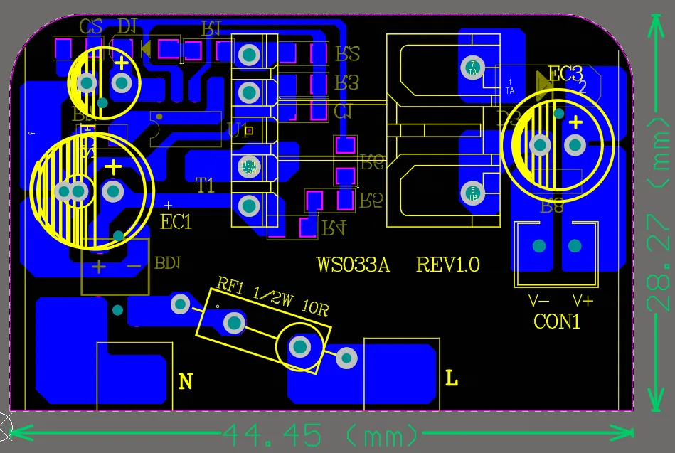
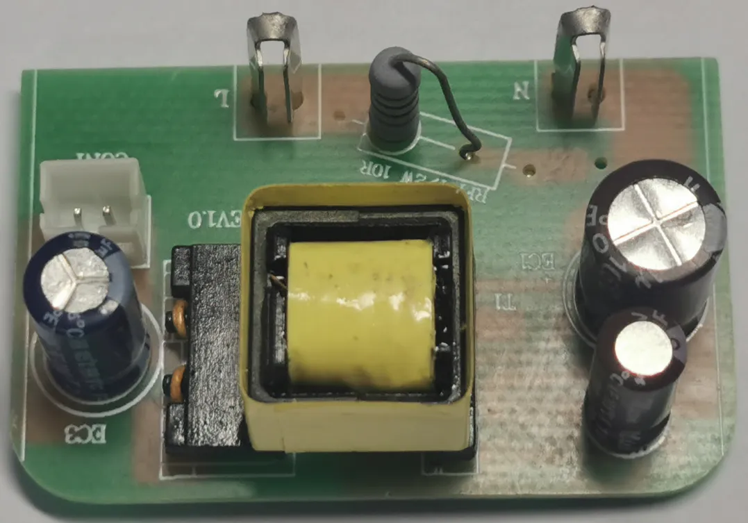
1. Introduction
1.1 Power Supply Overview
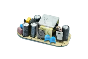
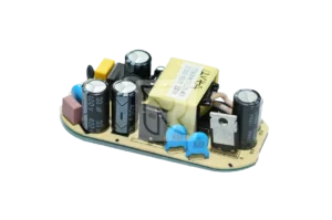
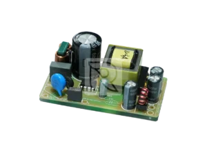
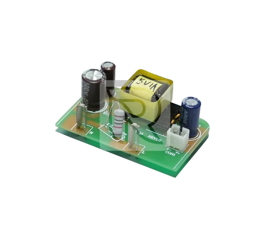
This adapter features high efficiency and high reliability, and also has the protections of SCP / OCP and OVP, etc.
Table 1: Power Supply Overview
| Input | Total Power | Efficiency | MTBF |
|---|---|---|---|
| 100Vac ~ 240Vac | 5W | ≥74% | ≥30K |
| Output | Regulation | Min. Current | Typ. Current |
| 5V | ±5% (full load) | 0A | 1.0A |
2. Electrical Specification
2.1 AC Input
2.1.1 Input Voltage
Table 2: List the AC input operating voltage range. The power shall work normally and meet all electrical requirements throughout the rated input voltage condition.
Table 2: AC Input Voltage Limitations
| Minimum | Rate | Maximum |
|---|---|---|
| 90Vac | 100Vac - 240Vac | 264Vac |
2.1.2 Input Protection Voltage
Table 3: AC Input Protection Voltage Limitations
| Undervoltage Protection | Undervoltage Protection Restore | Overvoltage Protection | Overvoltage Protection Restore |
|---|---|---|---|
| 60V | 75V | 300V | 285V |
2.1.3 Input Frequency
Table 4: List the AC input operating frequency range. The power shall work normally and meet all electrical requirements within the rated frequency condition.
Table 4: AC Input Frequency Limitations
| Minimum | Rate | Maximum |
|---|---|---|
| 47Hz | 60Hz/50Hz | 63Hz |
2.1.4 Inrush Current
At 25℃, when inputting the maximum voltage, the inrush current ≤50A
2.1.5 No Load Input Power
The no load input power should be no more than 0.1W under the rated input voltage condition.
2.1.6 Input Current Limiting
The input current should be less than 0.2A under the minimum AC input and full load.
2.1.7 Efficiency
The average efficiency is no less than 74%.
2.1.8 Power Fowtor
/
2.2 Output Specification
2.2.1 DC Output Voltage Range
Table 5: DC Output Voltage Limits
| Output | Min. | Typical | Max. | Unit |
|---|---|---|---|---|
| Io | 4.75 | 5 | 5.25 | V |
2.2.2 DC Voltage Regulation
The DC output voltages will remain within the regulation ranges shown in Table 6 when measured at the load end of the output connectors.
The voltage regulation limits do not include the transient DC load changes, which are covered in Section 3.2.5.
Table 6: DC Output Voltage Regulation Limits
| Output | Line Regulation | Load Regulation |
|---|---|---|
| Vo | ±5% | ±10% |
2.2.3 DC Output Current
Table 7: DC Output Current Limits
| Output | Minimum Load | Max Load | Peak Load | Unit |
|---|---|---|---|---|
| Vo | 0.01 | 1.0 | / | A |
2.2.4 Output Ripple and Noise
The following table 7 is the output ripple and noise requirements, which will be met throughout the load ranges specified in Section 3.2.3 and under the rated input voltage and rated input frequency conditions as specified in Section 3.1.1. The oscilloscope will be set to 20MHz bandwidth limit on measuring. The output terminal will be paralleled with one 0.1uF multilayer (type X7R) and one 10uF tantalum electrolytic (low ESR) capacitor.
Table 8: Output Ripples and Noise Limits
| Output | Max. |
|---|---|
| Vo | 250mV |
2.2.5 Output Dynamic Load Response
The output voltages will remain within the specified regulation limit of the nominal set voltage for changes in load as specified below under the following load steps defined below table 8. At a slew rate of 0.1Amps/uS between 50Hz to 10 KHz.
Table 9: Output Dynamic Load Response Limits
| Dynamic Load | Output Voltage Deviation Range |
|---|---|
| 10% ~ 100% ~ 10% | 10% |
| 10% ~ 50% ~ 10% | 10% |
| 50% ~ 100% ~ 50% 10% | 10% |
2.2.6 Overshoot at Turn - on / Turn - off
Any overshoot at turn on or turn off shall be less than 10% of the rated output voltage.
2.3 Protection Function
2.3.1 Over Voltage Protection
The power supply will provide over voltage protection function.
2.3.2 Short Circuit Protection
An output short circuit is defined as any output impedance of less than 0.1 ohms. The power supply will protect without damage to the overseers or the unit (components, connectors, etc) under the input conditions specified in Section 3.1 above.
2.3.3 Over Current Protection
The power supply has an OCP function, and without any damage during the test, the unit shall recover its functions automatically after the protection is removed.
Table 10: Over Current Protection Limits
| Output | Min | Max | Unit |
|---|---|---|---|
| V0 | 1.2 | 1.5 | A |
2.4 Timing
2.4.1 Start up Time
The start-up time shall be no more than 4 seconds at 115Vac/60Hz input, and no more than 3 seconds at 230Vac/50Hz input. The output loading should be set up with full load during the test.
3. Environment Requirement
3.1 Temperature
Operating Ambient: 0℃ ~ 40℃
Non - operating Ambient: -20℃ ~ +70℃
3.2 Humidity
Operating: 25% ~ 80% relative humidity (Non - condensing)
Non - operating: 10% ~ 90% relative humidity (Non - condensing)
3.3 Altitude
Operating: 5000 meters
Non - operating: 5000 meters
4. Mechanical Dimensions
5. Application Market
- Mobile phone charger for the elderly
- Home smart camera
- Li-ion battery charger
- Toy car charger
- Ebook reader
- Bluetooth headsets, small speakers, USB fans and other small electronic devices

